Valve Body Testing and Characterization Equipment
- Description
- System Features
- DOWNLOADS
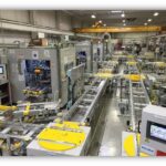
Description
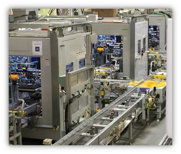
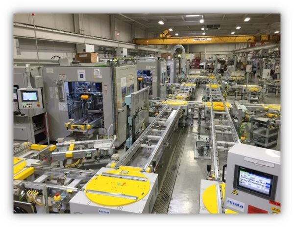
This system is one of many global systems we have built. Fully automated, it accepts a newly assembled transmission valve body, tests it as it would be testing in the transmission, including engaging electrical connectors, submerging in temperature controlled transmission fluid and loading the bolt locations with the appropriate force. Along with testing for flow and pressure, each solenoid is characterized for response and this data is later sent to the transmission controller for compensation. The process leaves the part wet, so it is then routed to a station within our system that vacuums and blows the remaining oil from the part.
We have installed these systems and support them all over the world, including Mexico, US and China.
Reasons For Testing
There can be inconsistencies in transmission valve body performance due to variations in assembly and consistency of individual components. This machine tests flow paths of each channel, functionality of each solenoid and characterizes the performance of those solenoids to that the transmission control module (TCM) can compensate for the variance. The machine clamps and submerges the whole VB assembly, while supplying ATF at pressure to simulate the final application conditions. Every solenoid is sequentially energized with a controlled electric current, commanded in steps ramping up and down for the full scale of operation. The software reads and saves the pressure, flow and response performance data that comes out of the VB tests. All the data collected, is matched with the serial number of the VB and is sent to a “cloud” server via MCVM. This is the characterization data that is later used by the Transmission Control Module, but is also part of the test records that are stored both locally and in a corporate database for later tracking.
- Single Test heads with moving sump
- Test time excluding fill and drain – 200 Sec.
- Test Oil Temperature adjustable 40 – 60° C. ±2 ºC in the tank
- Fluid supply range is 400 to 2200 kPa ± 3.5 kPa, capacity of 20 LPM.
- PT range 0 to 2500 kPa with accuracy error less or equal to +/- 0.05% FS BSL
- Coriolis flow meters, 3 total in each machine. 1 High, 1 Low, 1 Supply
- Adler Solenoid drivers utilizing a 32 MHz clock device with Infineon IC
- Part clamping up to 2,000 lb force at each bolt position
- Programmable test cycle