
Hydraulic Hybrid Transmission Testing & Test Stands
- Description
- DOWNLOADS
- Features
Description
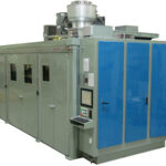
The MCM hydraulic hybrid transmission testing machine is designed to test hydraulic hybrid drive systems, being put to use on large commercial and industrial vehicles for the reduction in fuel consumption, brake wear, and CO2 emissions. The test machine is integral with the manufacturing process, and will accept post production assemblies to ensure validation of function, safety limits, and quality.
Hydraulic hybrid systems were developed as an alternative to battery-electric hybrid systems. They offer key advantages that make them a growing technology in reducing fuel consumption in the large commercial vehicle segment. Their designs utilize high pressure hydraulic motors, accumulators, valves, and control systems to capture regenerative braking energy; using this energy to propel the vehicle.
With a unique design and operating environment, high strength components and robust hydraulic systems must be ensured to be safe, leak free, function under extreme conditions, and meet high quality expectations. The MCM test machine system ensures these functions while simulating a dynamic environment, emulating the vehicle application. The machine checks component functions including spinning and absorbing power from the drive system.
This machine was designed to functionally test a hydraulic hybrid system designed for large refuse and delivery vehicles. The part being tested was the largest we’ve ever worked with weighing in at over 4000 pounds. The test performed was quite extensive taking nearly an hour to complete.
This bench performance tests a hydraulic hybrid for commercial vehicle applications. The test part was pulled into the machine on a cart that we designed. The operator manually connects motoring and absorbing drive/motor combinations to the input and output shafts of the hybrid to simulate the vehicle. The bench supplied two fluids (hydraulic oil & ATF) which were temperature controlled and automatically filled and evacuated. In line particle counters were utilized to ensure that both fluid systems were operating within required cleanliness boundaries.
The test involved full functional test of SAE J1939 communications between unit and vehicle plus calibration and verification of swash plate positioning in multiple pumps. The bench ran the part under test through its gear ranges and performed shift quality evaluations. Ability to generate and store high pressures was verified as well. A complete test report was generated at the conclusion of each test including any trapped error codes. The entire machine was surrounded by a custom sound enclosure to limit noise on the production floor.